2419 Feather Mae Ct, Forest Hill, MD 21050 | Phone: 410-340-9019
eMail List | News | Online Assembly Guide | Photo Gallery
|
2419 Feather Mae Ct, Forest Hill, MD 21050 | Phone: 410-340-9019 |
|
| Products | Order | Home |
Features & Specs |
Software |
Articles & Reviews |
Documentation eMail List | News | Online Assembly Guide | Photo Gallery |
Selectable Mic Filters
A selection of four mic filters offers
tailored audio input response when transmitting in voice modes (SSB or AM)
In response to requests for "more natural sounding voice" when transmitting in SSB and AM modes, we have provided audio filtering options that the Cube owner may choose from the new "Mic Filter" selection in the User Menu.
Background
In the original-issue I/O Boards, capacitor C3 value of .0047 uF provides a pre-emphasis to the incoming voice energy from the microphone that suppresses some of the low-end (bass) frequencies. This is a common practice in communications equipment which enables the available power of the transmitted signal to be applied more at the upper frequencies of the voice spectrum, which is when most of the intelligibility is contained. This allows the operator to have a better chance of being heard by DX contacts and when propagation is poor. (About 50% of the human voice energy is at the low frequencies, but 4-5% of the highest frequencies carry most of the intelligibility.)
The downside of this pre-emphasis is that the voice being transmitted does not sound as "normal or natural" because it lacks much of the low frequencies. This can be remedied by changing the shaping of the incoming voice energy being delivered by the microphone to give more bass response. But the trade-off is that transmit power is wasted when sending these low-information bass frequencies and thus less power is available for the higher voice frequencies ... resulting in possibly less of your signal being heard on the receive side of the QSO.
That all said, some Cube users would like to have their transmitted voices be more natural with a fuller, deeper sound on the receive side, which is a common desire when using AM modes or when having casual raw-chew QSOs. This condition can be acceptable when the propagation is good or if additional transmit power amplification is being used with the Cube ... it's up to the operator!
So ... in order to provide more flexibility and control, we have provided the user-selectable option to apply different audio shaping of the microphone input frequency response.
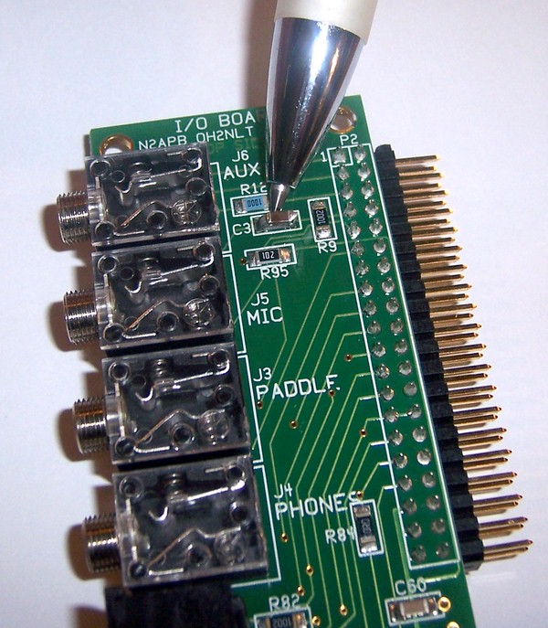
Optional Mod to C3 on the I/O BoardIf you wish to have four Mic Filter selections available, you will need to change the C3 capacitor on the I/O Board.
NOTE: This is completely optional. If you are not interested in achieving higher fidelity voice in SSB and AM transmit modes, you can do nothing and have your audio transmissions be just as they were before. When Mic Filter 0 (default setting) is used in conjunction with the original value for C3 (.0047 uF), the pre-emphasis will be applied just as before and no change from "stock" operation will be experienced.
But if you do wish to have control over what/how much filtering is applied to the mic input path, then all you need to do is tack a 0.1 uF capacitor across the exiting C3 cap on the I/O board, as shown below ...
With some care, adding a capacitor on top of the existing C3 can be done with the I/O Board in situ ... that is, while inside the Cube.
Note: All new Cubes (and I/O Boards) are now being shipped with C3 = 0.1 uF ... Thus, these new Cubes will have the full range of Mic Filtering available, as shown in the next section.
Mic Filters
The following table shows the audio frequency response of the microphone input when one of the four Mic Filters are selected from the User Menu.
The Default seeting is Mic Filter 0.
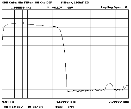
FILTER 0 ... with the change of I/O Board C3 to 0.1 uF
Notice that no filtering is provided and all the low-end (bass) voice energy will be transmitted, resulting in a very full, deep and power-inefficient transmission. While the voice transmission might sound more natural on the receiving side, sending the low voice frequencies like this wastes valuable Tx power, since most of the intelligible voice information is contained in the higher frequencies. Therefore this mode should only be used for casual QSOs when there is sufficient copy or when a power amplifier is being used. When DX'ing or when difficult propagation conditions are being experienced, Mode 1 should be used to apply more of the available Tx power to the intelligible portion of the voice energy.
FILTER 0 ... with no mod ... Original C3 of 0.0047 uF
This is the original frequency response of the SDR Cube mic input with the original value of C3. Thus when Filter 0 is selected, again there is no filtering, which allows the hardware (capacitor) to do the pre-emphasis filtering to provide better audio shaping for more voice information getting through on the transmission.
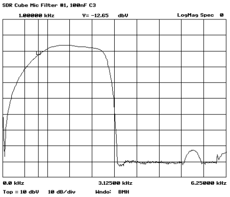
FILTER 1 ... Only applicable with the change of I/O Board C3 to 0.1 uF
This shaped audio response was created to match the original pre-emphasis provided with original-issue C3 (.0047 uF). So, by changing C3 to 0.1 uF and selecting Filter 1, the mic will have the ideal pre-emphasis applied for most effective use in making DX contacts.
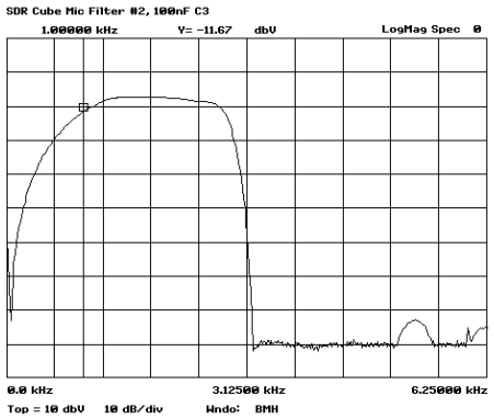
FILTER 2 ... Only applicable with the change of I/O Board C3 to 0.1 uF
This shaped audio response is a little narrower than Filter 1 and enables even more of the available Tx power to be applied to the higher voice frequencies, perhaps making the DX contacts even a bit easier to do.
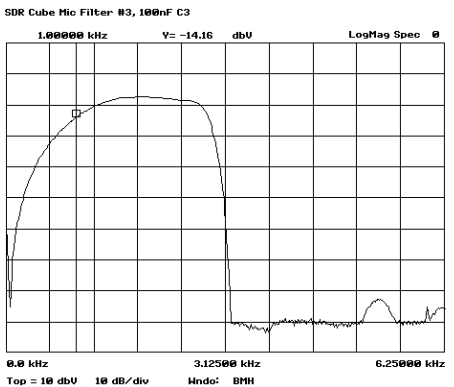
FILTER 3 ... Only applicable with the change of I/O Board C3 to 0.1 uF
This shaped audio response is the most narrow and probably too tight for effective voice communications. Perhaps useful only to experiment with.
Development & Engineering Background for the Mic Filter feature
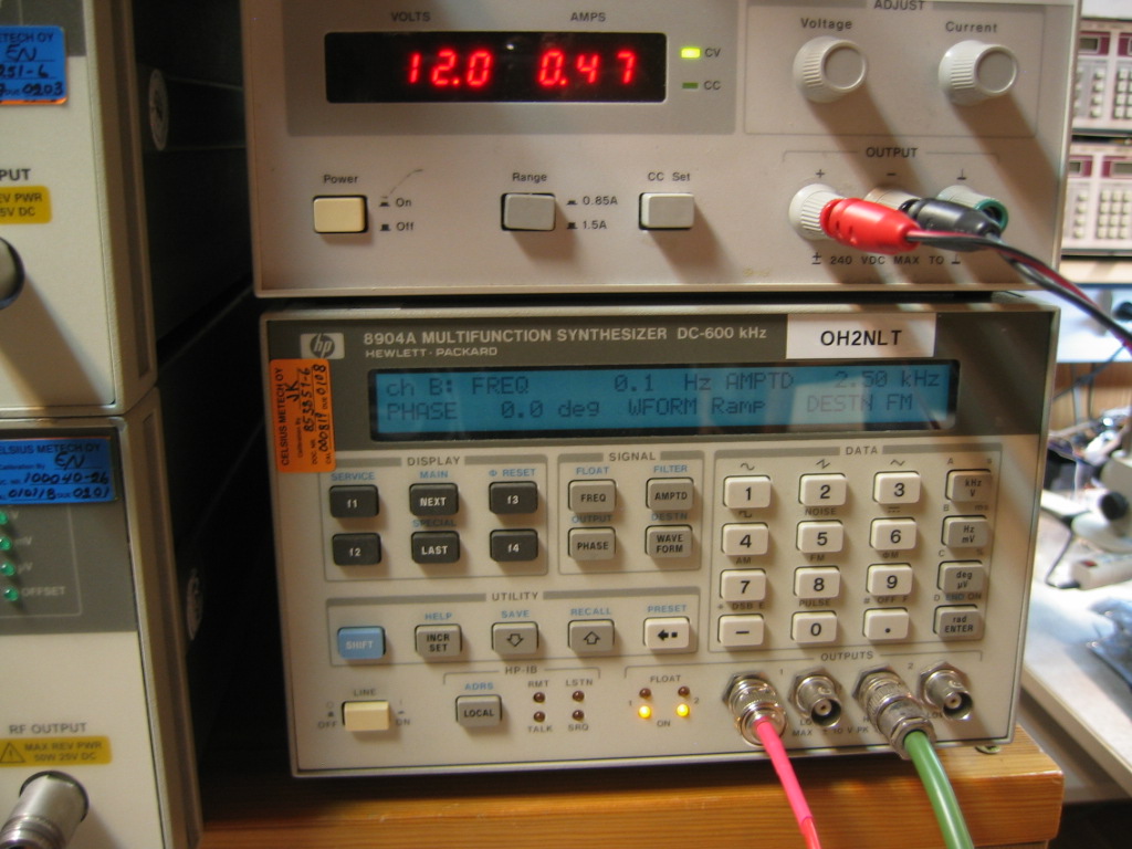
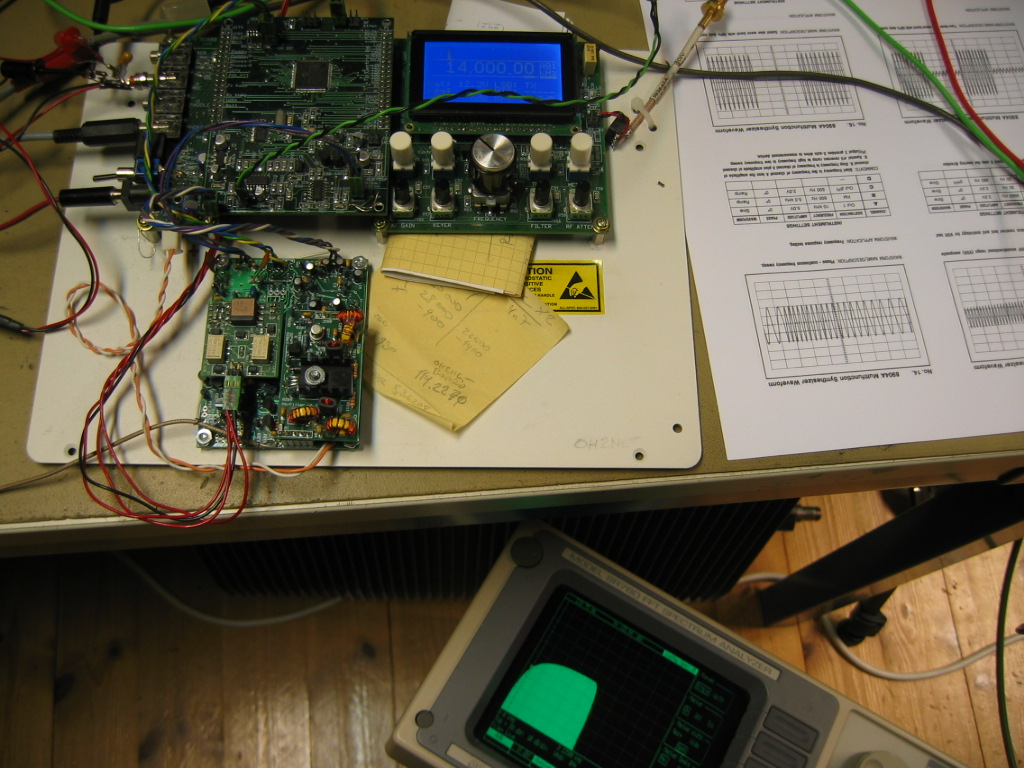
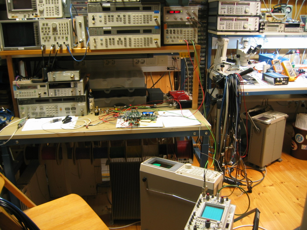
These photos illustrate the equipment and approach for measuring the Cube audio / SSB filters. The hp8904A synthesizer shows its superior capabilities, as shown in the hp8904 waveform cook book recipe #14 (hp document 5951_6715E.pdf).
An ordinary oscilloscope can be used as frequency response display (use XY mode).
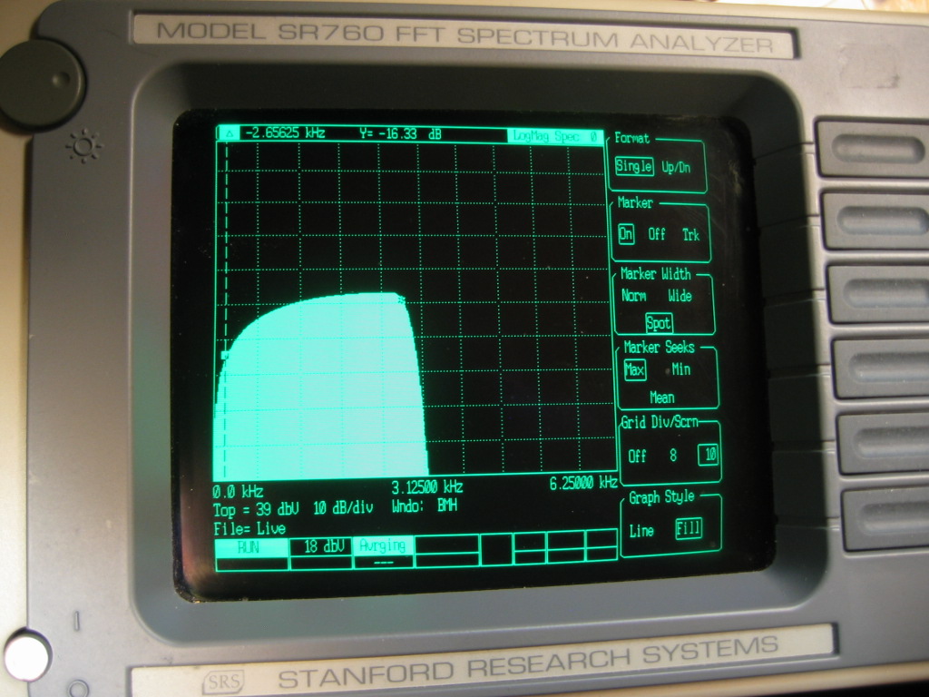
The response is also checked with an SR760 audio spectrum analyzer. You will see about the same shape in RF spectrum
With slow sweep speed you can also see the mic input signal shape from the Cube band scope display.
This test setup was
- 0-5kHz sine wave linear sweep to the mic input
- measurements from DSP board I/Q outputs and from antenna output
In the overall system frequency response you can notice very mild pre-emphasis done by the mic input hardware C3 = .0047 uF.
Copyright 2011-2013 Midnight Design
Solutions, LLC. All Rights Reserved.
![]()
Page last updated: August 31, 2013
.PNG)